«Last Updated on January 3, 2024 »
from Starfleet Prototype – The Journal of Innovative Design and Ideas, David Schmidt & Mastercom Data Center
NOTES:
Due to various perceived design faults in the Menahga (CG 3100) class battlecruiser prototype, the decision to proceed with the production of the class was a disputed one. However, the need for such a class was pressing, and final go-ahead for the ‘class’ production was given – with a provision. Thus, an R & D task force, was assigned to study the Menahga class’s inherent faults, with the objective of developing solutions which could be incorporated into as-yet unbuilt craft, and retro-fitted into already launched vessels.
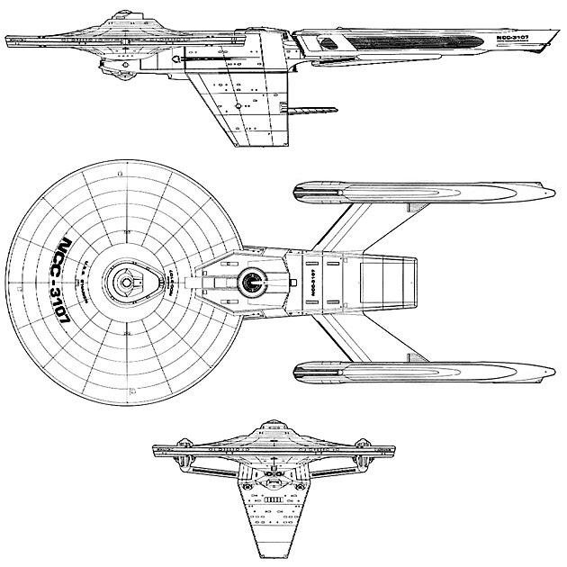
Complete redesign of the warp support hull, which houses the matter/antimatter reactor, intermix chamber, warp drive energy conduits, main energizer, and main engineering room. The new hull is larger and positioned higher, lairing into the rear of the central support hull, rather than being attached to the rear of the secondary hull. There are several advantages to this re-positioning. The major one is that the secondary hull can now be jettisoned without carrying the vessel’s warp support hull (and warp drive) along with it. This has allowed Starfleet Logistics to contemplate constructing various different secondary hulls for the class, which could be exchanged while the Battlecruiser is at any medium sized Starfleet facility (which could stock-pile a variety of the hulls. Options for these specialized hulls include the present Marine barracks/fighter craft hangar complex and cargo bay hull (MFHCCB), a dedicated cargo bay and cargo transporter hull (CBCT), a photon torpedo multi1ube launch hull (PTML), and a special mission weapons hull (SMW). Except for the first, all the above are purely speculative at this time.
A second advantage of the truly jettisoning secondary hull is that it offers the Captain yet another strategy. In the event that his ship is being chased and overtaken by superior forces, the Captain could initiate a “Jack-in-the-Box” maneuver. Rather drastic, it would begin by evacuating all Marines and ship’s support personnel from the secondary hull. Once emptied, the hull would be jettisoned while the ship was fleeing at warp speed. The secondary hull would quickly drop behind the vessel, passing out of the warp envelope and thus dumping into real space (moving at 0.99 C). There are two advantages in this maneuver. Firstly, it decreases the vessel’s tonnage by almost 25,000 metric tons, effectively converting the battlecruiser into a Thruxton (CT 2761) Tactical Cruiser, with that class’ speed. Secondly, the secondary hull has an auxiliary fusion powerplant, which is used to power flight deck functions during battle conditions. This reactor can be set to overload and detonate at a preset distance from the fleeing Battlecruiser. While unlikely to be a direct threat to the pursuing enemy vessels (which can evade the hull), the subsequent radia tion cascade might provide a sensor screen, in front of which the Battlecruiser can execute a new maneuver unseen. Redeployment of the warp drive nacelles to a position farther removed from the horizontal axis. This would improve the vessel’s warp dynamics while at the same time increase maneuverability. Replacement of the standardized (short) separate warp drive nacelle support struts with the new-concept one-piece strut, attaching same to the bottom of the warp support hull. This improves structural integrity, and allows for easier warp nacelle ejection. Addition of twin rear-firing torpedo tubes and bays, just below and forward of the warp nacelle support strut attachment point on the warp support hull.
Relocated rear phaser bank, with improved fire-arc. Redeployment of forward torpedo exhaust ports to the central sup port hull lower surface, aft of sensor suite.
Addition of a standardized sensor suite near the customary position, displaced to make room for the forward torpedo bay. Relocation of the Hangar Bay to the rear of the secondary hull, and the addition of an external landing platform. Addition of internal energy conduits and external hardpoints for megaphaser cannon – presently left unmounted.
Trial results were a definite improvement upon the Menahga class, and plans are being made to recall most of the present battlecruiser fleet back to Spacedock for refit, although some of the original Battlecruiser (such as USS Menahga) may be left intact. Like the Menahga class, the S’harien class battlecruisers is assigned to the Rapid Deployment Fleet.
| Construction Data: | ||||||
| Model – | Mk I | Mk II | Mk III | Mk IV | Mk V | Mk VI |
| Ship Class – | X | X | X | X | X | X |
| Date Entering Service – | 2288 | 2298 | 2303 | 2318 | 2338 | 2355 |
| Number Constructed – | 10 | Refit | Refit | Refit | Refit | Refit |
| Hull Data: | ||||||
| Superstructure Points – | 28 | 28 | 30 | 30 | 31 | 40 |
| Damage Chart – | C | C | C | C | C | C |
| Size: | ||||||
| Length – | 320 m | 320 m | 320 m | 320 m | 320 m | 320 m |
| Width – | 141 m | 141 m | 141 m | 141 m | 141 m | 141 m |
| Height – | 78 m | 78 m | 78 m | 78 m | 78 m | 78 m |
| Weight – | 156,130 mt | 156,130 mt | 159,690 mt | 159,420 mt | 158,521 mt | 153,312 mt |
| Cargo: | ||||||
| Total SCU – | 470 SCU | 470 SCU | 470 SCU | 470 SCU | 470 SCU | 470 SCU |
| Cargo Capacity – | 23,500 mt | 23,500 mt | 23,500 mt | 23,500 mt | 23,500 mt | 23,500 mt |
| Landing Capacity – | None | None | None | None | None | None |
| Equipment Date: | ||||||
| Control Computer Type – | M-6a | M-6a | M-6a | M-6a | I-5 | I-6 |
| Transporters: | ||||||
| Standard 6-person – | 3 | 3 | 3 | 3 | 3 | 3 |
| Emergency 22-person – | 4 | 4 | 4 | 4 | 4 | 4 |
| Cargo – | 3 | 3 | 3 | 3 | 3 | 3 |
| Other Data: | ||||||
| Crew – | 310 | 315 | 318 | 319 | 322 | 326 |
| Passengers – | 40 | 40 | 40 | 40 | 40 | 40 |
| Shuttlecraft – | 14 | 14 | 14 | 14 | 14 | 14 |
| Engines And Power Data: | ||||||
| Total Power Units Available – | 76 | 76 | 76 | 76 | 80 | 84 |
| Movement Point Ratio – | 4/1 | 4/1 | 4/1 | 4/1 | 4/1 | 4/1 |
| Warp Engine Type – | FWG-1 | FWG-1 | FWG-1 | FWG-1 | FWG-1 | FNWD-2b |
| Number – | 2 | 2 | 2 | 2 | 2 | 2 |
| Power Units Available – | 26 ea. | 26 ea. | 26 ea. | 26 ea. | 26 ea. | 27 ea. |
| Stress Chart – | D/F | D/F | D/F | D/F | D/F | C/D |
| Max Safe Cruising Speed – | Warp 8 | Warp 8 | Warp 8 | Warp 8 | Warp 8 | Warp 8 |
| Emergency Speed – | Warp 10 | Warp 10 | Warp 10 | Warp 10 | Warp 10 | Warp 10 |
| Impulse Engine Type – | FIG-1 | FIG-1 | FIG-1 | FIG-1 | FIH-1 | FIJ-3 |
| Power Units Available – | 24 | 24 | 24 | 24 | 28 | 30 |
| Weapons And Firing Data: | ||||||
| Beam Weapon Type – | FH-3 | FH-3 | FH-3 | FH-3 | FNH-1 | FNH-9 |
| Number – | 6 | 6 | 6 | 6 | 6 | 6 |
| Firing Arcs – | 2 f/p, 2 f/s, 2 a | 2 f/p, 2 f/s, 2 a | 2 f/p, 2 f/s, 2 a | 2 f/p, 2 f/s, 2 a | 2 f/p, 2 f/s, 2 a | 2 f/p, 2 f/s, 2 a |
| Firing Chart – | W | W | W | W | W | W |
| Maximum Power – | 5 | 5 | 5 | 5 | 6 | 12 |
| Damage Modifiers: | ||||||
| +3 | (1-10) | (1-10) | (1-10) | (1-10) | (1-15) | (1-7) |
| +2 | (11-17) | (11-17) | (11-17) | (11-17) | (16-18) | (8-15) |
| +1 | (18-20) | (18-20) | (18-20) | (18-20) | (19-20) | (16-20) |
| Beam Weapon Type – | FH-9 | FH-11 | FH-14 | FH-18 | FNH-15 | FNH-28 |
| Number – | 2 | 2 | 2 | 2 | 2 | 2 |
| Firing Arcs – | 2 f | 2 f | 2 f | 2 f | 2 f | 2 f |
| Firing Chart – | X | Y | T | Y | W | Y |
| Maximum Power – | 6 | 10 | 12 | 12 | 15 | 20 |
| Damage Modifiers: | ||||||
| +3 | (-) | (1-10) | (-) | (1-10) | (1-7) | (-) |
| +2 | (1-12) | (11-17) | (1-10) | (11-17) | (8-15) | (-) |
| +1 | (13-22) | (18-24) | (11-18) | (18-24) | (16-20) | (1-22) |
| Torpedo Weapon Type – | FP-4 | FP-4 | FP-9 | FP-9 | FP-9 | FP-23 |
| Number – | 4 | 4 | 4 | 4 | 4 | 4 |
| Firing Arcs – | 2 f, 2 a | 2 f, 2 a | 2 f, 2 a | 2 f, 2 a | 2 f, 2 a | 2 f, 2 a |
| Firing Chart – | S | S | R | R | R | S |
| Power to Arm – | 1 | 1 | 1 | 1 | 1 | 1 |
| Damage – | 20 | 20 | 28 | 28 | 28 | 36 |
| Shield Data: | ||||||
| Deflector Shield Type – | FSS | FSS | FSS | FSS | FSQ | FST |
| Shield Point Ratio – | 1/4 | 1/4 | 1/4 | 1/4 | 1/4 | 1/4 |
| Maximum Shield Power – | 20 | 20 | 20 | 20 | 30 | 45 |
| Combat Efficiency: | ||||||
| D – | 176 | 176 | 178.9 | 178.9 | 202.3 | 241.2 |
| WDF – | 96.8 | 106.2 | 119.2 | 127 | 131.6 | 190 |